Flow Sensor 1.5 inch Manufacturer

Sale!

Original price was: ₹3,000.00.Current price is: ₹1,500.00.

- +
Guaranteed Safe Checkout

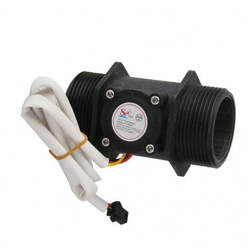
The flow sensor 1.5 inch is a plastic-body water flow sensor for industrial flow measurement and controller feedback. It uses a rotor and Hall-effect pulse output for water-flow monitoring in suitable utility and process applications.

  • Source-listed operating range: 1 to 120 L/min with ±2% accuracy claim in the supplied copy
  • DC 5 to 24V operating voltage mentioned in the product data
  • Hydrostatic pressure above 1.75 MPa noted in the source
  • Medium temperature listed up to 120°C in the supplied copy
  • Manufactured at UMA Industries’ unit in Village Sunped, Ballabgarh, Faridabad, Haryana, India
  • UMA Industries supplies and provides technical support across India

Published website prices are company-confirmed, and quotation-stage size, power, mounting and transport details may be finalized to suit the application.

UMA Industries manufactures and supplies flow sensor 1.5 inch units for industrial water-flow measurement from its unit in Village Sunped, Ballabgarh, Faridabad, Haryana, India. This compact plastic-body sensor is used where a rotating water rotor and Hall-effect pulse output are preferred for controller feedback, flow display, and total-volume monitoring. UMA Industries supplies and provides technical support to customers across India, and the published website prices are company-confirmed. For buyers planning a project around a flow sensor 1.5 inch, the page is intended to help with technical review, quotation preparation, and application matching before purchase.

The supplied product copy describes a simple working principle. Water moves through the rotor assembly, rotor speed changes with the flow rate, and the Hall-effect sensor generates a corresponding pulse signal. A controller can then interpret those pulses to estimate flow speed or accumulated volume. That makes the sensor relevant for compact automation panels, utility water lines, and machine-level monitoring where a pulse input is easier to process than a more complex instrument. The source text also states that the sensor may be connected to a digital flow controller using red for positive, yellow for signal output, and black for negative.

Applications for the flow sensor 1.5 inch

The flow sensor 1.5 inch is suited to water-based applications where operators want flow awareness, batch counting, or automatic control feedback. The supplied copy mentions water heaters, water vending machines, credit card operated water machines, and flow measurement devices. In practical plant use, the same principle is often helpful in rinse lines, water supply loops, compact process systems, and small utility skids where the control panel needs a pulse signal rather than a large standalone meter.

For OEM builders and maintenance teams, the advantage is often simplicity. A rotor-and-sensor design can be easier to integrate into a compact machine design, and the pulse output can be counted or displayed by a suitable controller. This is useful when the application needs a repeatable signal for flow indication, volume tracking, or basic interlock logic. Because the product page is based on the supplied copy, buyers should still confirm the exact liquid, pipe size, and controller input before finalizing selection.

If your panel project needs related counting or timing functions, you may also review the Digital Counter or the Counter with Timer. These internal references can support a broader control solution when the flow sensor is only one part of the system.

Selection guidance before ordering

Choosing a flow sensor 1.5 inch is not only about pipe size. The actual selection should also consider the liquid medium, expected flow range, controller compatibility, installation orientation, and the level of signal conditioning required in the final panel. The supplied source data lists an accuracy statement of 1 to 120 L/min at ±2%, a hydrostatic pressure value above 1.75 MPa, operating voltage of DC 5 to 24V, and a medium temperature limit up to 120°C. These details are useful for comparison, but they should still be matched carefully to the real process conditions.

For quotation preparation, it is good practice to note the intended line size, whether the sensor is being used for display only or for closed-loop control, and whether the controller expects a pulse output exactly as shown in the product copy. It is also helpful to confirm the supply voltage at the installation point and whether the electrical cabinet already has a pulse input channel. UMA Industries confirms website prices, while product size, capacity, internal and external dimensions, power supply, optional controls or accessories, and transport mode may be finalized or adjusted in the quotation or proforma invoice according to customer requirements.

What to check with the process team

Before ordering, the process team should verify the medium, expected operating flow, and whether the line is clean enough for rotor-based measurement. The sensor page is written around water, so buyers should confirm any requirement beyond water before committing to purchase. Also confirm whether the controller will totalize pulses, display flow rate, or trigger valve action. This avoids mismatches between the sensor output and the way the machine logic is programmed.

How the sensor operates

The operating principle is straightforward. As water enters the flow rotor assembly, the magnetic rotor rotates. When flow increases, the rotor speed changes accordingly. The Hall-effect sensor reads the movement and outputs corresponding pulses. The controller receives those pulses and converts them into flow information or volume counts. This is why pulse calibration in the controller matters: the sensor provides the signal, while the controller determines how the signal becomes a displayed value.

The supplied text also states that the sensor is lightweight, small in size, and easy to install. It mentions an inlaid stainless steel impeller shaft, a sealing structure designed to reduce leakage, and resistance to violent shock and chemical erosion as described in the source copy. These points are useful for buyers comparing physical design, but installation quality remains important. Even a compact sensor should be handled carefully during piping, alignment, cable routing, and start-up testing.

Installation notes and mounting precautions

Installation orientation has a direct effect on rotor movement and signal stability. The source copy says the sensor should be mounted vertically and should not exceed 5 degrees inclination. In practical terms, that means the line should be planned so the rotor can move freely and the signal remains consistent at the intended operating conditions. It is also sensible to keep the cabling protected from pulling or vibration, especially in panels mounted on mobile skids or machines with frequent start-stop cycles.

When wiring the unit, the supplied product copy states red for positive, yellow for signal output and black for negative. That information is helpful, but the controller input should still be checked before energizing the circuit. If the controller expects a dry contact, 4-20 mA input, or another signal format, the installation should be reviewed by the project engineer. For pulse-count applications, a simple bench check at low flow can confirm whether the controller is reading pulses correctly before the system is released for production use.

For related instrumentation on the same website, buyers may also review the TDS meter modbus rtu rs485 when a project needs water-quality data alongside flow monitoring. That combination can be useful in treatment, reuse, and utility applications where multiple measurements are tracked in one control panel.

Technical points from the supplied product copy

The product text provides several practical reference points for engineering review. It lists hydrostatic pressure above 1.75 MPa, an operating voltage range of DC 5 to 24V, an insulation resistance value above 100M, and an accuracy statement in the 1 to 120 L/min range. It also mentions low-temperature and high-temperature checks: after exposure to -20°C for 72 hours and to 85°C for 72 hours, the first measurement accuracy is said to remain within ±5% after returning to room temperature for one hour. These figures are retained from the source copy for evaluation, not as a substitute for final application testing.

The source also includes the flow pulse relationship F = 0.45 × Q, where Q is in L/min. Buyers should use this as a data point for controller setup if it matches the intended pulse interpretation in their system. Because totalizer performance depends on controller logic and installation conditions, it is best to verify the pulse conversion during commissioning rather than relying only on a catalog number. This is especially important in machines that meter water for dispensing, dosing, or batch control.

Routine verification and maintenance

Maintenance for the flow sensor 1.5 inch should be simple but regular. Keep the line clean so the rotor can move without unnecessary resistance. Inspect the body, cable and connector area during planned shutdowns. Check that the sensor remains in its intended mounting position and that there is no external stress on the pipework. If the process shows unstable readings, first verify the controller input, wiring polarity, and supply voltage before replacing the sensor.

Calibration or field verification is usually application-specific for a pulse sensor of this type. The controller must be configured to interpret the pulses correctly, so commissioning should include a check against a known water volume or a stable operating point. If the final displayed value does not match expectation, review the pulse-per-litre setting, the flow profile, and any installation restriction that may be affecting the rotor. In many cases, a careful wiring check and orientation review solve issues faster than component replacement.

For panel builders and machine users who need a simple count-and-display strategy, the Digital Counter and the Human Sensing Timer can be useful internal references. They help illustrate how a pulse or trigger signal can be handled in a broader automation layout.

Why the product is practical for industrial buyers

The appeal of this sensor lies in the combination of compact size, pulse output, and water-flow monitoring use case. Industrial buyers often need a device that is easy to install, straightforward to wire, and suitable for use inside a control sequence. The source copy describes the sensor as a plastic-body water flow sensor with a rotor and Hall-effect sensor, which makes it suitable for situations where the controller does the interpretation and display. This approach is common in compact machines that must track water use without adding a bulky meter assembly.

Because UMA Industries manufactures this product in Faridabad and supports buyers across India, customers can review the requirement with a local manufacturing unit while still planning site use for plants in other regions. This is helpful when a project needs a quotation that reflects the actual installation details, transport mode, and controller arrangement. The company’s published website prices are company-confirmed, and the quotation stage can address any size, mounting, supply, or accessory changes needed for the application.

Faridabad manufacturing and India-wide support

Manufactured at UMA Industries’ unit in Village Sunped, Ballabgarh, Faridabad, Haryana, India, the flow sensor 1.5 inch is offered with pan-India technical support. That makes it easier for buyers to discuss system compatibility, controller matching, and installation planning before purchase. If you are preparing a quotation for a line upgrade or a machine build, it is useful to share the expected flow range, medium, mounting position, and control objective so the team can align the sensor choice with the final use case.

Published prices on the website are company-confirmed. Product size, capacity, internal and external dimensions, power supply, optional controls or accessories, delivery schedule and mode of transport may be finalized or changed according to customer requirements in the quotation or proforma invoice. Ready-stock compact products, controllers, spares and accessories may be dispatched by air courier within 3 working days, subject to availability, payment confirmation, destination serviceability and carrier schedules. Delivery timelines for complete salt spray chambers and other large equipment are confirmed separately according to model, capacity, packing and freight mode.

Frequently asked questions

Is the flow sensor 1.5 inch meant for water?

The supplied product copy is written around water flow measurement and water-based applications. Buyers should confirm any non-water liquid use before ordering.

What kind of output does it provide?

The source states that the Hall-effect sensor provides a pulse signal that can be read by a controller for flow and volume calculations.

What supply voltage is listed in the product data?

The supplied copy lists DC 5 to 24V operating voltage. Final controller compatibility should be checked during selection.

Can it be used for water vending or dispensing equipment?

Yes. The source specifically mentions water vending machines and related flow measurement devices among the intended applications.

How should the wiring be connected?

The source text lists red as positive, yellow as signal output and black as negative. Wiring should always be verified against the controller before powering the system.

Does installation orientation matter?

Yes. The supplied copy says the sensor should be mounted vertically and should not exceed 5 degrees inclination.

What should be checked during maintenance?

Inspect cleanliness, rotor movement, cable condition, mounting stability and pulse consistency. These checks help keep the reading stable in service.

Can I use related instruments with it?

Yes. Depending on the project, related products such as the Dosing Pump Timer can support control logic, while a Digital Counter can support pulse display or counting.

Request a quotation

If you need a dependable flow sensor 1.5 inch for industrial water measurement, UMA Industries can help review your line conditions, wiring plan and controller input before you place an order. Share the flow range, medium, mounting requirement and panel details so the quotation can be prepared around your application. For broader project needs, UMA Industries also supplies and provides technical support across India from its Faridabad manufacturing unit.

When the sensor is part of a larger monitoring or control system, it is best to align the flow sensor 1.5 inch with the rest of the panel at the quotation stage. That allows the customer and the UMA Industries team to confirm the practical details without assuming anything beyond the supplied product facts.

Selection Guidance for flow sensor 1.5 inch

Use the verified product configuration, installation conditions and required control functions when selecting flow sensor 1.5 inch.


Need help choosing? Call/WhatsApp us for industrial pH/ORP solutions.


Weight300 g
Dimensions6 × 6 × 6 cm

Reviews

There are no reviews yet.

Be the first to review “Flow Sensor 1.5 inch Manufacturer”
🟢 WhatsApp Price 📞 Call Now
Scroll to Top