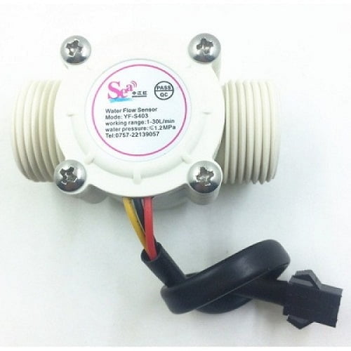
UMA Industries manufactures and supplies the Flow Sensor 3/4 inch for water flow monitoring, pulse feedback and controller integration in practical industrial and utility applications. The product is built around a compact rotor-and-sensor arrangement that converts water movement into a signal the connected controller can read. For buyers comparing a Flow Sensor 3/4 inch with a meter, timer or control device, the key advantage is simple installation, dependable pulse output and a form factor that suits space-conscious panel and equipment builds.
Published website prices are company-confirmed. Product size, power supply, accessory options, wiring details, delivery schedule and transport mode may be finalized in quotation according to the application. That flexibility is useful when the same Flow Sensor 3/4 inch is being matched with a water heater line, a vending system or a general-purpose flow indication circuit.
Flow Sensor 3/4 inch for industrial and utility applications
The Flow Sensor 3/4 inch is suited to installations where water flow needs to be detected, counted or used as an input for switching and control. The source copy identifies use in water heaters, water vending machines, credit card machines and flow measurement devices. In practice, this makes it relevant for small equipment builders, service technicians, utility panels and OEM-style assemblies that need a compact sensor rather than a full flow display.
Because the sensor generates a signal corresponding to flow, it can support controller logic, run indication and simple process interlocks. Buyers often pair a sensor like this with a Digital Counter or Counter with Timer when flow events need to be counted, batched or displayed locally. In control-oriented builds, it may also be paired with a Dosing Pump Timer for timing-related liquid handling tasks, depending on the final panel design.
For projects that also need signal handling or status logic, the Human Sensing Timer and Digital Length Meter are examples of nearby control products in the same website ecosystem, useful when the application expands beyond basic flow detection.
How to select the right Flow Sensor 3/4 inch
Selecting the right Flow Sensor 3/4 inch begins with the operating medium, the expected flow range, the supply voltage available in the panel and the signal input style required by the downstream controller. The supplied product information states a working voltage range of DC 5-18V, a lowest rated working voltage of DC 4.5-5V to 24V, and a flow range of 1-30 L/min. These values should be matched to the actual application and wiring plan before purchase.
Application fit and installation checks
Check whether the line is intended for water only, how the sensor will be mounted and whether the flow path can support the installation orientation. The source content notes vertical mounting and that inclination should not exceed 5 degrees. It also states that the medium temperature should not exceed 120 ℃ and the working temperature should not exceed 80 ℃, so system conditions must be confirmed at the quotation stage. If the installation includes water quality or liquid monitoring alongside flow input, a TDS meter modbus rtu rs485 or a PH Sensor Lab Glass 1 Meter Cable may be specified separately as part of a broader process package.
The Flow Sensor 3/4 inch is particularly useful where a small sensor body is preferred and the system designer wants a direct pulse signal instead of a bulky transmitter. The red, yellow and black wire identification supplied in the source copy should be followed during installation, along with the controller manual.
Operating principle of the this product
The sensor operates by using a rotor assembly and Hall current sensing arrangement. When water passes through the body, the rotor turns, and the Hall sensor generates a pulse output corresponding to the flow. As flow increases or decreases, the pulse frequency changes accordingly, allowing the connected controller to interpret the signal.
This makes the this product suitable for control circuits that need a basic, low-volume sensing method. It is not a substitute for an engineered process flow transmitter where a higher-grade signal chain, display logic or networking may be required. Instead, it is a practical sensor for everyday monitoring, counting and feedback tasks in compact systems.
Installation and operating procedure
Before installation, confirm the line size, thread match and available DC supply. The source specifies a 3/4 inch external thread and indicates the wiring colors as red positive, yellow signal output and black negative. Install the sensor in a way that supports the recommended orientation and protects the body from unnecessary vibration or mechanical shock. The product description also mentions resistance to chemical erosion and a durable stainless steel impeller shaft, which is useful in routine service environments.
During operation, keep the sensor within its specified electrical and temperature limits. If the system is used in a heater, vending or dispensing line, the controller should be tuned to the actual pulse behavior of the installed unit. Where the application includes switching, counting or batching, the final control logic should be tested with real flow conditions instead of assuming nominal performance.
Routine calibration and verification for the Flow Sensor 3/4 inch
The this product should be verified against a known flow condition after installation. Routine checks normally include confirming that pulses are generated consistently, comparing indicated flow with a reference method, and checking that the controller interprets the signal correctly at low, mid and higher flow points within the working range. If the application is critical, verification should be repeated after maintenance, line cleaning or wiring changes.
Because the product is used as a sensing device rather than a self-calibrating instrument, the system integrator should confirm the site method for acceptance. This is especially important when the sensor feeds an automatic controller, a timer sequence or a water dispensing logic board.
Maintenance and service guidance
Regular maintenance helps preserve signal consistency. Keep the flow path clean, inspect the wiring for secure terminations and check for signs of leakage at the threaded connection. The source copy mentions a seal ring and upper/lower force structure; in practical use, that means proper fit-up and correct tightening matter. Avoid unnecessary impact, twisting or rough handling during service.
If the sensor is installed in a water heater or beverage-related system, periodic inspection is sensible because scale, sediment or trapped debris can affect rotor movement. A basic maintenance routine should include observing the pulse output at normal operating flow, confirming that the sensor remains aligned with the pipe and ensuring the system remains within the stated voltage and temperature limits.
Safety precautions
For safe use of the this product, disconnect power before rewiring, use the correct DC supply and avoid exposing the sensor to conditions beyond the stated medium temperature and working temperature limits. Do not use it where pressure, vibration or chemical exposure exceeds the intended service condition. The source copy notes an allowable pressure of 1.75 MPa, which should be checked against the actual installation design before final use.
Electrical safety also depends on correct grounding, stable controller input and proper insulation of exposed conductors. If the sensor is part of an automated system, the installer should validate the signal direction and logic before handing the equipment over to the end user.
Faridabad manufacturing origin and pan-India support
This this product is manufactured at UMA Industries’ unit in Village Sunped, Ballabgarh, Faridabad, Haryana, India. That manufacturing origin is valuable for customers who want a local industrial supply source with technical support that can be coordinated across India. UMA Industries supplies and provides technical support to customers across India, which helps project teams, OEM buyers and maintenance users source the sensor with practical pre-sales assistance.
For buyers in Faridabad, Ballabgarh and nearby industrial belts, the local manufacturing base can simplify technical discussion, wiring clarification and quotation alignment. For outstation buyers, the pan-India support model allows the product to be specified for different equipment builds without relying on a distant generic marketplace listing.
Quotation, pricing and dispatch notes
The website price for the this product is company-confirmed. Product size, capacity-related application details, supply voltage, accessories and transport mode may be finalized or changed in quotation according to the customer requirement. If your application needs the sensor bundled with a controller, counter or timer, the exact combination can be aligned before proforma invoice.
Ready-stock compact products, controllers, spares and accessories may be dispatched by air courier within 3 working days, subject to availability, payment confirmation, destination serviceability and carrier schedules. Delivery timelines for larger assemblies are confirmed separately according to the final model and freight plan. Please use the quotation stage to confirm the wiring requirement, operating voltage and application fit for the this product.
FAQs
What is the main use of the Flow Sensor 3/4 inch?
It is mainly used for water flow detection, pulse feedback and controller input in systems such as water heaters, water vending equipment and compact flow measurement devices.
What kind of output does the this product provide?
The source copy identifies a Hall current sensor arrangement that outputs a corresponding pulse signal to the controller.
What flow range is mentioned for the this product?
The supplied product information states a flow range of 1-30 L/min, which should be matched to the actual application.
Can the sensor be used with different DC supplies?
The source states a working voltage range of DC 5-18V and a lowest rated working voltage of DC 4.5-5V to 24V. The final selection should match the panel and controller design.
How should the this product be installed?
The source copy says it should be mounted vertically and should not exceed 5 degrees inclination. Thread fit, wiring and line conditions should be checked before operation.
Is the this product suitable for heated water lines?
The source copy mentions that medium temperature should not exceed 120 ℃ and working temperature should not exceed 80 ℃. The installer should confirm the full system condition before use.
Can this sensor be paired with a counter or timer?
Yes. Because it provides pulse output, it can be used with suitable counters, timers or controller inputs depending on the final circuit design.
How do I order the this product?
Use the quotation or contact process to confirm your application, supply voltage, wiring requirement and quantity. UMA Industries can then align the product with the required system configuration.
For technical selection, pricing confirmation or quotation support, contact UMA Industries for the Flow Sensor 3/4 inch. The team can help match the sensor to your application, wiring and controller requirements before dispatch.
Flow Sensor 3/4 inch is supplied with the final configuration recorded in the customer quotation or proforma invoice.
Need help choosing? Call/WhatsApp us for industrial pH/ORP solutions.


Reviews
There are no reviews yet.