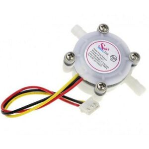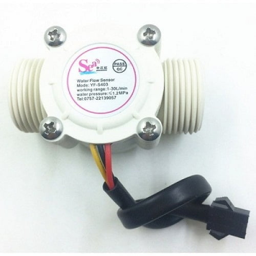
UMA Industries manufactures and supplies the Flow Sensor 1/4 inch for compact liquid flow measurement where a small threaded sensor, pulse output and simple controller integration are required. This model is used in water-handling equipment, appliance circuits and process skids that need a practical 1/4 inch solution with low-flow sensing. Manufactured at UMA Industries’ unit in Village Sunped, Ballabgarh, Faridabad, Haryana, India, it is supplied with pan-India technical support and quotation flexibility for application matching.
The Flow Sensor 1/4 inch is a useful fit for OEM panels, small water systems, dosing-related lines and other installations where the signal must be read by a controller or digital input. The published product data supports a flow range of 1–5 L/min, G1/4" thread size, DC 5–18V working voltage range and a pulse output that can be integrated into flow-counting or display systems. For buyers comparing compact flow sensing options, this model offers a focused choice rather than an oversized meter body.
Published prices on the website are company-confirmed. Product size, capacity, internal and external dimensions, power supply, optional controls/accessories, delivery schedule and mode of transport may be finalized or changed according to customer requirements in the quotation or proforma invoice. That flexibility is helpful when the sensor is being paired with a specific controller, cable, enclosure or plumbing arrangement.
Flow Sensor 1/4 inch applications in water systems
The Flow Sensor 1/4 inch is typically selected where low-volume water flow must be detected or counted reliably. In practical terms, it is suited to compact equipment that benefits from a small installation footprint and a simple digital signal. Common use cases from the supplied source include water heaters, water vending machines and flow measurement devices, along with other light-duty liquid circuits that work within the specified limits.
Because the unit is designed around pulse output, it can be connected to a controller that interprets frequency as flow rate or total volume. This makes the sensor useful for OEM builds, service retrofits and test benches where the objective is to observe water movement, totalize usage or trigger a control action when flow is present.
Where this sensor fits best
For engineering teams, the main advantage is compactness: the 1/4 inch connection supports small-bore piping, while the low-flow range helps in applications that do not need a larger industrial meter. It is also suitable where installation space is limited and the signal can be processed by a basic digital input or a dedicated flow controller. If the project requires other instrumentation around the panel, related products such as Digital Counter and Counter with Timer may be relevant for pulse counting or elapsed-time-based control.
Technical selection guidance
Before choosing the Flow Sensor 1/4 inch, match the sensor to the actual line conditions instead of selecting only by thread size. Confirm the liquid is compatible with the sensor’s wetted materials and operating conditions, then check whether the expected working range stays within the stated 1–5 L/min band. The source also states a maximum medium temperature of 120 ℃, a working temperature of up to 80’C, a humidity range of 35%–90%RH and a water pressure limit below 1.75Mpa.
Electrical compatibility matters as much as plumbing. The product data lists a minimum rated working voltage of DC 5~24V, a working voltage range of DC 5~18V, maximum working current of 15mA at DC 5V and load capability of up to 10mA at DC 5V. In a real installation, the controller input, cable length, supply quality and grounding practice should be matched during quotation and panel design. If the sensor is part of a larger automation system, a related product such as Digital Length Meter can be reviewed alongside the pulse processing arrangement.
Selection Guidance for Flow Sensor 1/4 inch
For best results, treat wiring, mounting orientation and signal conditioning as part of the selection stage. The source notes that the sensor should be installed vertically and should not exceed 5 degrees inclination. That makes mechanical layout important in pump rooms, equipment cabinets and compact skids. A properly planned installation reduces nuisance readings and simplifies maintenance later.
Working principle and output signal
The supplied description identifies the unit as a small turbine-type sensor whose output is a series of digital pulses. In use, the flow of liquid turns the rotor assembly, and the pulse frequency changes with flow rate. This is a straightforward method for converting movement of water into an electrical signal that a controller can read directly.
The product text also describes Hall-based pulse reading and controller feedback for display of flow speed and total volume. In practice, that means the sensor is most useful when paired with a device that can count pulses, convert frequency to rate, or accumulate total passage over time. For buyers building a simple metering point, the sensor gives a direct signal path without the complexity of a large transmitter package.
Because the output is digital rather than analog in the source description, signal interpretation depends on the controller or PLC logic. This is why installation planning should include the full measurement chain: sensor, cable, input type and display method. If the application needs other panel accessories, a Digital Counter or Dosing Pump Timer may be part of the system design, depending on the control objective.
Installation and operating procedure
Install the sensor on a suitable 1/4 inch line with the correct flow direction and a stable mechanical support. The source advises vertical mounting and keeping inclination within 5 degrees. Before first use, verify electrical polarity and signal lead connection with the controller wiring. The supplied lead identification is Red for positive, Yellow for signal output and Black for negative.
Once connected, start with clean water and observe that the controller receives pulses as flow begins. Increase flow gradually within the stated range and confirm that the output changes smoothly. If the application includes hot water or a heated circuit, respect the medium temperature limit from the product data and avoid operation above the stated limits. For any system with water quality changes, viscosity change or air entrainment, field observation is important during commissioning.
In day-to-day use, keep the line filled and avoid shock loading, dry running or uncontrolled pressure spikes. The source states that the seal structure is intended to resist leakage, but stable mechanical and hydraulic conditions still matter for dependable service. If the sensor is added to a broader instrumentation panel, related products such as Humidity Sensor may help in cabinet-environment monitoring, especially where condensation risk needs attention.
Commissioning checklist
Check the controller input type, verify the wiring, confirm the sensor is mounted vertically and ensure the expected flow is inside the stated operating band. Then compare the displayed rate or pulse count against the process condition so that the operator understands what the signal means in practice. This simple verification step often prevents confusion later.
Calibration, routine verification and maintenance
The Flow Sensor 1/4 inch is a pulse-output device, so routine verification is usually more relevant than a complex calibration ritual. After installation, compare the sensor output with a known process condition or a controlled test volume to confirm that the controller counts pulses correctly. If the equipment is used for billing, process recording or recurring batch work, routine check intervals should be defined by the plant’s own quality practice.
Maintenance should focus on keeping the flow path clean, checking the mounting angle, inspecting the cable and confirming that the signal is stable during operation. The source notes the presence of an inlaid stainless steel impeller shaft, a durable wearable construction and chemical erosion resistance. Those are useful design features, but they do not remove the need for periodic inspection, especially where water quality is variable or particles may be present.
If the sensor is part of a serviceable assembly, keep spare connectors or associated panel items ready as required. For buyers who need related control components, options such as tds meter modbus rtu rs485 can be reviewed for water-quality monitoring in the same project environment, while the flow sensor handles movement measurement.
Safety precautions and installation limits
Good installation practice is essential for stable operation. Do not exceed the stated medium temperature, pressure or electrical range. Avoid severe vibration, piping strain and improper orientation. The product text also warns against strong shock and notes that the sensor should not be subjected to rough handling. In panel work, make sure supply polarity is correct before energizing the circuit.
If the application is near hot water circuits, heaters or vending equipment, keep the sensor accessible for inspection and avoid placing it where service access is blocked. Cable routing should be neat and protected from abrasion. In wet or humid installations, use suitable enclosure practice to preserve signal integrity and reduce connector corrosion.
Faridabad manufacturing, pan-India support and quotation process
UMA Industries manufactures the Flow Sensor 1/4 inch in Faridabad and supports customers across India with product guidance and technical assistance. This is useful for buyers in OEM procurement, maintenance stores, panel shops and water-equipment assembly units that need a dependable source and practical after-sales communication. The company’s published prices are company-confirmed, while final configuration can be aligned during quotation or proforma invoice preparation.
For related system planning, buyers often review nearby instrumentation from the same catalogue alongside the sensor, particularly when they need pulse counting, timers or panel indicators. A coordinated purchase can simplify wiring, reduce mismatch and make installation easier for the service team. If you are building a new machine or replacing an older sensor, please share the process details, line conditions and controller input requirements for quotation support.
Selection notes for OEMs and service teams
OEM buyers usually care about repeatability, simple wiring and a compact footprint, while service teams often care about quick replacement and compatibility with the existing controller. The Flow Sensor 1/4 inch addresses both by offering a small-body 1/4 inch connection and a pulse signal that can be used in a range of light liquid systems. When the application involves a new enclosure or control panel, it is wise to confirm cable routing, connector space and the display method before ordering.
If your project also needs auxiliary sensing or control, you can review related items such as Human Sensing Timer for automation logic and Reject and Good Pcs detector for count-based process monitoring. Those products are not substitutes for flow sensing, but they may help complete a larger control solution.
FAQs
What is the Flow Sensor 1/4 inch used for?
The this product is used for compact water flow measurement where a small threaded sensor and pulse output are needed. It is suitable for water heaters, water vending machines and similar liquid-handling equipment mentioned in the product data.
What is the flow range of the this product?
The supplied specification lists a flow range of 1–5 L/min. Buyers should confirm that their normal working flow stays within that band before finalizing the installation.
How is the sensor wired?
The source states Red for positive, Yellow for signal output and Black for negative. Wiring should always be checked against the controller input and installation practice before power-up.
Can the this product be used with hot water?
The product data says the medium temperature should not exceed 120 ℃ and the working temperature is listed as up to 80’C. For hot-water applications, the actual line conditions should be confirmed during quotation and commissioning.
Does the sensor need vertical installation?
Yes, the source says it should be mounted vertically and should not exceed 5 degrees inclination. Correct orientation helps the rotor move properly and supports stable pulse output.
Is this sensor suitable for counting total water usage?
Yes, it can be used with a controller that reads pulse frequency and totalizes volume. The final display or total count depends on the controller logic and calibration practice.
What power supply does the this product need?
The product data lists a minimum rated working voltage of DC 5~24V and a working voltage range of DC 5~18V. The correct supply must match the controller and the installation design.
How often should the sensor be checked?
Routine verification depends on how critical the measurement is in the process. For recurring production, billing or batch work, the sensor output should be checked periodically against a known condition.
Where is the this product manufactured?
It is manufactured at UMA Industries’ unit in Village Sunped, Ballabgarh, Faridabad, Haryana, India, with pan-India support available for customers.
Request a quotation
If you need the this product for a new machine, replacement requirement or OEM build, share your line size, liquid type, flow range and controller input details. UMA Industries can help align the sensor with the application and quotation requirements, with support across India from the Faridabad manufacturing unit.
For a practical, compact flow measurement solution, the Flow Sensor 1/4 inch remains a straightforward choice for pulse-based water flow monitoring in small systems.
Need help choosing? Call/WhatsApp us for industrial pH/ORP solutions.


Reviews
There are no reviews yet.