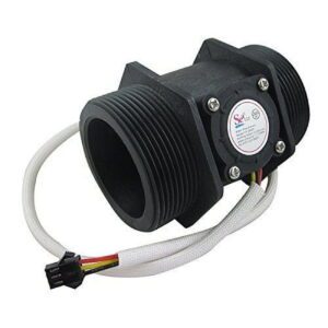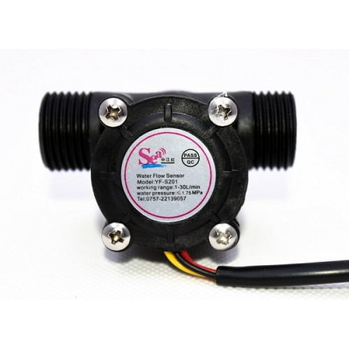
Flow Sensor 1/2 inch

Sale!

Original price was: ₹2,450.00.Current price is: ₹500.00.

- +
Guaranteed Safe Checkout

Flow Sensor 1/2 inch is a compact Hall-effect water flow sensor for pulse-based flow measurement in water systems. Manufactured by UMA Industries at Village Sunped, Ballabgarh, Faridabad, it is suited to controllers, microcontrollers and Arduino-based projects.

  • Hall-effect sensor with 3-wire pulse output
  • Working voltage: 5 to 18V DC
  • Working flow rate: 1 to 30 L/min
  • Accuracy: ±10%
  • Maximum water pressure: 2.0 MPa
  • UMA Industries supplies and provides technical support across India

Ready-stock compact products and accessories may be dispatched by air courier within 3 working days, subject to availability and carrier schedules.

UMA Industries manufactures and supplies Flow Sensor 1/2 inch from its unit in Village Sunped, Ballabgarh, Faridabad, Haryana, India. This compact Hall-effect water sensor is designed for pulse-based flow measurement in water lines, helping users monitor consumption, automate control logic and improve process visibility in small water management systems. For buyers comparing a Flow Sensor 1/2 inch with other meter options, the key advantages are simple wiring, low power demand and easy integration with controllers, microcontrollers and Arduino boards.

Flow Sensor 1/2 inch for water measurement applications

The sensor works in line with the water pipe and uses a pinwheel rotor plus an integrated magnetic Hall-effect element to generate an electrical pulse with each revolution. The controller reads these pulses and converts them into flow speed and total volume passed through the sensor. In practical use, Flow Sensor 1/2 inch is suitable for water heaters, vending-type water systems, credit-card or token-based dispensing setups, laboratory or utility water control panels and compact flow measurement devices. Buyers who need a simple pulse-output element for a controller-driven system often prefer this type because it is straightforward to mount, wire and verify during setup.

For broader automation projects, you can also review related devices such as Digital Counter, Counter with Timer, Dosing Pump Timer and Human Sensing Timer when a project needs counting, timing or control logic around the flow signal.

Selection guidance for the right installation

Selecting a Flow Sensor 1/2 inch should begin with the intended medium, pipe arrangement and controller input method. The published technical data supports water applications with a working voltage of 5 to 18V DC, a tested minimum working voltage of 4.5V, a working flow rate of 1 to 30 liters per minute, a maximum water pressure of 2.0 MPa and an accuracy of ±10%. These figures make the sensor suitable for many compact water circuits, but the final selection should always match the actual flow band in your application rather than a generic catalogue assumption.

The quotation stage is the right time to finalize any system-dependent details such as mounting arrangement, signal interpretation, cable routing and controller compatibility. Published prices on the website are company-confirmed. Product size, capacity, internal and external dimensions, power supply, optional controls/accessories, delivery schedule and mode of transport may be finalized or changed according to customer requirements in the quotation or proforma invoice. That flexibility is helpful when a project team is matching the sensor to an existing panel or to a new controller design.

Working principle of Flow Sensor 1/2 inch

The sensor contains a rotor that turns as water passes through the body. The magnetic element and Hall-effect sensing arrangement create a pulse train that can be counted by a controller. This approach is useful where the operator wants both instantaneous flow indication and accumulated quantity. A standard relationship supplied for this model is frequency (Hz) = 7.5 × flow rate (L/min), and the sensor is also listed with 450 pulses per liter. As with any pulse sensor, the controller logic should be set up to interpret the output according to the actual calibration approach used in the project.

Wiring and controller compatibility

Flow Sensor 1/2 inch has three wires and can be interfaced with a microcontroller or Arduino board. The supplied wire assignment is simple: Red for positive (+), Yellow for signal output and Black for negative (-). Keep the wiring neat, use suitable connectors, and ensure the controller input is compatible with a 5V TTL pulse output. In systems with long cable runs or noisy electrical environments, careful routing and grounding practices are important so that the pulse signal remains stable. If your panel already uses a monitoring or counter device, the flow signal can be brought into that system for display or logic control.

Operating procedure and routine verification

Before putting the sensor into regular service, mount it in the flow line so that the direction and physical position are correct. The product note states that it should be mounted vertically and should not exceed 5 degrees inclination. The medium temperature should not exceed 120 ℃. Once installed, run water through the line, confirm that the signal is appearing at the controller and verify that the reading changes smoothly with flow. Because every application has its own plumbing layout and control logic, the commissioning step should include a short functional check with known operating conditions.

Routine verification is especially useful in systems where an operator depends on the reading for dosing, billing, batch filling or interlocked control. A periodic check against a measured volume or a known container can confirm that the pulse count is still matching the expected relation. If the reading appears unstable, the usual causes are incorrect wiring, air bubbles, pipe disturbance, mounting issues or controller configuration rather than a problem with the sensor body itself.

Flow Sensor 1/2 inch calibration and signal check

For simple project work, calibration means confirming that the pulse count reported by the controller corresponds to the volume actually delivered. Start with clean water, keep the installation condition steady, and compare the totalized value with a measured container or test volume. If your application uses a custom conversion factor, store that factor in the controller logic and document it for future maintenance. This is often the easiest way to make Flow Sensor 1/2 inch perform consistently across repeated batches or repeated fills.

Maintenance, safety and long-term care

Maintenance for this type of sensor is generally practical and straightforward. Keep the water path reasonably clean, avoid debris that could disturb the rotor, and inspect the installation periodically for leaks, vibration or loose wiring. The product description notes that the seal ring and upper/lower force structure are intended to support leak resistance, while the stainless-steel impeller shaft is chosen for wear resistance. As with any in-line sensor, good maintenance also means avoiding mechanical shock and keeping the sensor within its operating limits.

For safety, do not exceed the listed temperature and pressure conditions, and do not treat the output signal as a substitute for a proper process design review. When the sensor is used in automated systems, the controller should be configured so that alarms, counters and pumps respond predictably. If the application is exposed to chemicals or unusual liquids, confirm suitability before use because the published data supplied here is for water-oriented flow measurement.

Faridabad manufacturing origin and pan-India support

Flow Sensor 1/2 inch is manufactured at UMA Industries’ unit in Village Sunped, Ballabgarh, Faridabad, Haryana, India. That manufacturing base supports quick commercial coordination, technical guidance and consistent documentation for Indian buyers. UMA Industries supplies and provides technical support to customers across India, which is useful for OEMs, panel builders, system integrators and maintenance teams that need a reliable flow-sensing component for local assembly or retrofit work.

Ready-stock compact products, controllers, spares and accessories may be dispatched by air courier within 3 working days, subject to availability, payment confirmation, destination serviceability and carrier schedules. Delivery timelines for larger or model-specific equipment are confirmed separately according to model, capacity, packing and freight mode. For this page, that means the sensor can usually be coordinated more quickly than a complete engineered machine, while still following the actual order and logistics conditions.

Related devices for control panels and instrumentation

Buyers often pair a flow sensor with adjacent panel components that help count, time or control the output signal. Depending on the system design, helpful related pages may include Digital Length Meter, Reject and Good Pcs detector, Tip and Bit Detector Controller and Digital Humidity Meter. These links are not substitutes for the sensor, but they can help builders complete the surrounding measurement or control package.

Frequently asked questions

1) What is the main use of this product?

It is used to measure water flow by generating pulses that a controller can count and convert into flow rate and total volume.

2) Can this product connect to Arduino?

Yes. The product note states that it has three wires and can be easily interfaced between a microcontroller and an Arduino board.

3) What is the working voltage of this product?

The supplied technical specification lists 5 to 18V DC as the working voltage, with a minimum tested working voltage of 4.5V.

4) What is the flow range for this sensor?

The listed working flow rate is 1 to 30 liters per minute, so the application should be matched to that operating band.

5) Is this product suitable for high pressure?

The published maximum water pressure is 2.0 MPa. Always confirm that the actual system pressure stays within the stated limit.

6) How should this product be mounted?

The product information states that it should be mounted vertically and should not exceed 5 degrees inclination.

7) What output signal does this product provide?

It provides a 5V TTL pulse output with each rotor revolution, which the controller can interpret for flow measurement.

8) How should I verify the reading after installation?

Run water through the system, compare the controller reading against a measured volume and confirm that the pulse-to-volume conversion is consistent.

9) Is the sensor suitable for every liquid?

The supplied page content supports water-oriented use. If your medium is different, confirm compatibility before ordering.

10) How can I order this product from UMA Industries?

You can contact UMA Industries for quotation, technical clarification and dispatch coordination. Share your flow range, controller type and installation requirement so the right support can be given.

If you need a compact, pulse-output water sensing component for a control panel, Flow Sensor 1/2 inch is a practical option for measurement, monitoring and simple automation. Contact UMA Industries for selection help, quotation support and pan-India supply coordination.


Need help choosing? Call/WhatsApp us for industrial pH/ORP solutions.

Weight300 g
Dimensions6 × 6 × 6 cm

Reviews

There are no reviews yet.

Be the first to review “Flow Sensor 1/2 inch”
🟢 WhatsApp Price 📞 Call Now
Scroll to Top