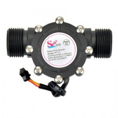
UMA Industries manufactures and supplies the 1 inch Water Flow Sensor for practical liquid flow measurement in compact water systems, dispenser lines, beverage equipment and other pulse-counting applications. This 1 inch Water Flow Sensor is designed around a rotor-and-hall-effect sensing principle, making it suitable when the buyer needs a simple electrical pulse output for monitoring or controller input rather than a heavy industrial meter body.
Because buyers often search for a quick-fit sensor and a dependable signal source, this product is positioned for straightforward integration with a digital flow controller or count-based display. The 1 inch Water Flow Sensor is useful where the line size, installation space and electrical interface matter as much as the flow reading itself. For many OEM and replacement users, the main buying decision is not only the range, but also fitment, wiring clarity and stable pulse generation.
Manufactured at UMA Industries’ unit in Village Sunped, Ballabgarh, Faridabad, Haryana, India, this sensor also benefits from the company’s India-wide supply and support approach. UMA Industries supplies and provides technical support to customers across India, which is especially helpful when the same sensor is being evaluated by equipment assemblers, service teams and maintenance buyers in different states.
In the website catalogue, this product is a value-focused option with company-confirmed pricing, and the quotation can be aligned to the actual buying need. Product size, capacity, internal and external dimensions, power supply, optional controls/accessories, delivery schedule and mode of transport may be finalized or changed according to customer requirements in the quotation or proforma invoice. That flexibility matters when the sensor is being paired with a controller, cable assembly or OEM panel layout.
Typical applications for the 1 inch Water Flow Sensor
This sensor is commonly selected where a compact water flow signal is required for counting, monitoring or controller logic. The 1 inch Water Flow Sensor can be considered for water dispensers, coffee machines, small water circuits, laboratory utility lines and other equipment where a low-power pulse output is preferred. It is also relevant for service replacement work when the existing installation already uses a similar rotor-type sensor and the objective is compatibility rather than a complete redesign.
In buyer discussions, application fit normally depends on fluid type, expected flow band, electrical input requirements and the available mounting orientation. For that reason, this sensor should be matched to the actual system conditions rather than chosen only on connector appearance. If the application needs display counting, simple control input or logging through a controller, the pulse output can be used as part of the system design.
Where the 1 inch Water Flow Sensor fits best
For OEM builders and maintenance teams, the 1 inch Water Flow Sensor is useful in compact systems that need a small physical footprint and direct pulse output. It is particularly relevant when the installation expects the sensor to be fitted in-line and read by a controller or counter that interprets pulse frequency as flow. The stainless steel impeller shaft, light-weight body and sealing arrangement support routine use in water-service environments.
Where the unit is used in dispensers or beverage equipment, the priority is usually repeatable signal generation and simple maintenance. In those cases, the sensor is better viewed as a practical system component than as a standalone instrument. Buyers should also consider whether the matching electronics are already available, because the sensor’s value is highest when its pulse signal is used correctly in the control loop.
Selection guidance before ordering
When choosing a water flow sensor, first confirm that the line size and the system’s expected flow band fit the application. The 1 inch Water Flow Sensor has a stated flow rate range of 2~100 L/min, so the buyer should compare that band with the actual operating demand of the line. If the system runs at very low flow or outside that range, another sensing arrangement may be more appropriate.
Next, check the supply voltage and signal input arrangement. This product is specified with a minimum working voltage of DC 4.5V and a working voltage of DC 5V~18V. That means the installer should confirm the available electronics before finalizing the purchase. The sensor also provides a pulse relationship of f=(4.8*Q), with Q expressed in L/min, which helps when the output is being interpreted by a digital flow controller or counter.
Finally, consider mounting conditions, piping orientation and the liquid temperature. The product notes specify vertical mounting and no more than 5 degrees inclination, while the medium temperature should not exceed 120 ℃. These are practical selection checks, not just installation preferences, because the sensor’s performance depends on being fitted in the intended orientation.
Matching with controllers and display units
The sensor is commonly used with a digital flow controller or a counting/display device that can read pulse input. When pairing electronics, the installer should confirm signal polarity and the expected pulse interpretation. The available wiring guidance is straightforward: Red for positive, Yellow for signal output and Black for negative. This makes the sensor easy to integrate into many common low-voltage systems where a simple pulse output is enough.
For system builders, the key question is not only whether the sensor fits physically, but whether the controller can count the pulses correctly. If the final assembly is part of a machine, dispenser or water-treatment subassembly, the controller logic, cable routing and protection of the signal line should be checked during quotation and panel design.
Operation and wiring overview
Once installed in the correct orientation, the 1 inch Water Flow Sensor produces a pulse signal as water moves the rotor. That signal can then be used to monitor flow or count passage over time. In practical use, the sensor should be mounted vertically and kept within the stated inclination limit so that rotor movement remains stable and the pulse output remains usable for the connected controller.
The product description indicates that the sensor is light-weight, small in size and easy to install. It also notes a stainless steel impeller shaft and a sealing structure intended to reduce leakage risk. Those features are useful in service environments where technicians want a quick replacement and a familiar electrical interface. The installation should still respect the medium-temperature limit and pressure requirements given in the product facts.
Basic operating points for the 1 inch Water Flow Sensor
Before putting the unit into service, confirm that the supply voltage is within the stated range, the flow direction is correct for the system layout and the signal wire is connected to the intended controller input. If the connected device expects a different pulse count logic, that should be set in the receiving equipment rather than assumed at the sensor end. In many projects, the sensor is only one part of a larger measurement system, so the final reading depends on the complete setup.
Calibration and routine verification
The this product is a pulse-output device, so routine verification is usually done by comparing its signal with a known test volume or with a trusted reference arrangement in the system. Buyers should align the controller scaling, if any, with the actual pulse relationship stated for the product. This is particularly important when the sensor is used for counting, batching or logged flow monitoring.
Routine verification should also confirm that the sensor still turns freely in the process stream, that the wiring remains secure and that the displayed or counted output remains stable at expected operating points. If the application is critical, the customer should define the verification interval according to their own maintenance plan and process requirements.
Maintenance and service care
Maintenance for a compact rotor-type sensor is generally practical and straightforward. The flow path should be kept clean enough to avoid avoidable rotor fouling, and the sensor should not be exposed to installation shock or conditions outside the stated medium-temperature limit. Because the body is described as resistant to chemical erosion and built with a durable impeller shaft, routine inspection is usually focused on mechanical condition, seal integrity and signal consistency.
If the pulse output becomes unstable, the technician should inspect the mounting orientation, the electrical connections and the system’s own controller logic before assuming the sensor itself has failed. This approach reduces unnecessary replacement and helps distinguish between wiring issues, process condition changes and actual sensor wear.
Safety and installation precautions
Install the sensor only in the intended vertical orientation and avoid exceeding the stated inclination limit. Do not use the unit outside the specified temperature or voltage band. Also ensure that the connected equipment is compatible with the sensor’s pulse output and that the wiring is protected from accidental shorting, moisture ingress or strain at the terminals.
Where the sensor is used in beverage or dispensing equipment, the installer should confirm that the process liquid, pressure condition and cleaning practice are suitable for the line materials used in the full assembly. The sensor should be treated as one element in the system, not as a substitute for proper process design.
Faridabad manufacturing origin and pan-India supply
Customers often need a supplier who can support both new installation and replacement work. Manufactured at UMA Industries’ unit in Village Sunped, Ballabgarh, Faridabad, Haryana, India, the this product is backed by a manufacturing origin that is easy to document for procurement and service records. UMA Industries supplies and provides technical support to customers across India, which helps teams working on OEM builds, panel assemblies and field replacements.
For order planning, remember that published prices on the website are company-confirmed, while product size, capacity, internal and external dimensions, power supply, optional controls/accessories, delivery schedule and mode of transport may be finalized or changed according to customer requirements in the quotation or proforma invoice. This keeps the buying process practical for both standard purchases and customized system integration.
Related products and internal resources
For systems that use counters, timers or connected control logic, buyers may also review Counter with Timer or Digital Counter. If the project needs additional sensing or control components, Dosing Pump Timer and tds meter modbus rtu rs485 can be useful companion pages for broader system planning.
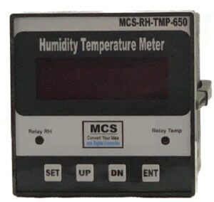
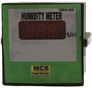
When the installation includes other instrumentation or environmental monitoring, you can also compare Humidity Sensor and PH Sensor Lab Glass 1 Meter Cable. These related pages help buyers map a complete control or measurement setup rather than focusing on a single component in isolation.
Frequently asked questions
1) What is the main use of the this product?
It is used for water flow measurement through pulse output, especially in compact systems such as dispensers, coffee machines and similar water circuits.
2) What flow range does the sensor support?
The stated flow rate range is 2~100 L/min. Buyers should confirm that their operating flow lies within this band before ordering.
3) What voltage is required?
The minimum working voltage is DC 4.5V and the working voltage is DC 5V~18V. The connected electronics should be matched to this requirement.
4) How is the sensor wired?
Red is positive, Yellow is signal output and Black is negative. The receiving controller should be compatible with pulse input.
5) Does installation orientation matter?
Yes. The sensor should be mounted vertically and should not exceed 5 degrees inclination for proper operation.
6) Can it be used with a digital controller?
Yes. The product information specifically notes that it should be connected with a digital flow controller, provided the controller is compatible with the pulse output.
7) Is the medium temperature limited?
Yes. The temperature of the medium should not exceed 120 ℃.
8) Where is this product manufactured and supported?
It is manufactured at UMA Industries’ unit in Village Sunped, Ballabgarh, Faridabad, Haryana, India, and UMA Industries supplies and provides technical support across India.
9) How should buyers plan quotation-stage details?
Published prices are company-confirmed, but product size, capacity, internal and external dimensions, power supply, optional controls/accessories, delivery schedule and mode of transport may be finalized or changed according to customer requirements in the quotation or proforma invoice.
If you need a practical, compact and easy-to-integrate pulse sensor, the 1 inch Water Flow Sensor is a sensible choice for selected water measurement applications. Contact UMA Industries for quotation support, application matching and pan-India technical assistance.
1 inch Water Flow Sensor is supplied with the final configuration recorded in the customer quotation or proforma invoice.
Need help choosing? Call/WhatsApp us for industrial pH/ORP solutions.


Reviews
There are no reviews yet.