Liquid Flow Meters Manufacturer

Sale!

Original price was: ₹9,000.00.Current price is: ₹5,500.00.

- +
Guaranteed Safe Checkout

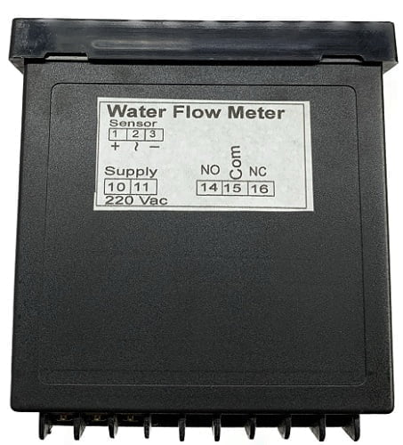
Liquid Flow Meters from UMA Industries are microcontroller-based digital panel instruments for measuring water and other clean liquids using pulse-input flow sensors. They show instant flow rate and totalized volume on a bright LCD and are suitable for industrial control panels.

  • 16×2 LCD showing flow rate and total volume
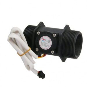
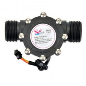
  • Pulse input from turbine / multi-jet type flow sensors
  • Two relay outputs for pump, valve or alarm control
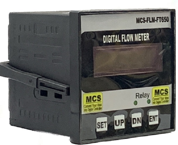
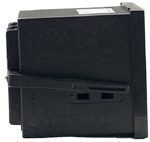
  • 96×96 mm panel-mount format with 220 VAC supply
  • Password-protected calibration through front keys
  • Manufactured at Village Sunped, Ballabgarh, Faridabad, with pan-India support

Published prices are company-confirmed, and product size, power supply, accessories and delivery schedule may be finalized in quotation as required.

UMA Industries manufactures and supplies Liquid Flow Meters for industrial water and clean-liquid measurement. The product is manufactured at UMA Industries’ unit in Village Sunped, Ballabgarh, Faridabad, Haryana, India, and UMA Industries supplies and provides technical support to customers across India. This panel-mounted instrument is intended for users who need a clear flow rate reading, a stable totalizer and practical relay-based control in a compact control-panel format. The website price is company-confirmed for this product, while the final configuration can be aligned to the application during quotation.

Liquid Flow Meters for industrial water and clean liquids

Liquid Flow Meters are designed for continuous monitoring of water and other compatible clean liquids when a pulse-output flow sensor is available. The meter accepts pulse signals from turbine / multi-jet type flow sensors and converts those pulses into a live flow indication and a cumulative volume indication. Operators can therefore see both the instant rate and the total discharge without switching screens or relying on a separate counter.

In practical plant use, this helps with transfer supervision, utility balancing, batch control and line verification. When the reading must be visible at the panel door, a compact LCD flow meter is often more convenient than a large supervisory system or a handheld instrument. The 96×96 mm format also makes the unit suitable for OEM panels, retrofits and utility cabinets where space needs to be used efficiently.

The meter is built around a microcontroller-based design with simple front keys, so routine setup can be completed from the panel itself. The same basic unit can serve different pipe sizes and flow ranges once the correct sensor and pulse-per-litre value are selected. That flexibility is useful for buyers who need one model that can be adapted to multiple lines in the same factory.

Typical applications and local industrial use

Liquid Flow Meters are commonly selected for RO, DM and softener plant water monitoring, process water lines, boiler and cooling water circulation, chemical dosing and batching systems, and OEM integration in washing, filling and packaging machines. They are also useful for general utility metering where the operator wants a compact panel display with totalization and relay outputs.

For industrial users in and around Faridabad, Ballabgarh and the wider NCR manufacturing belt, these meters are practical in water treatment skids, process-line panels and machine-mounted control boxes. They suit sites where operators want to verify flow, compare discharge against batch targets, or monitor whether a pump and valve sequence is behaving as expected. Because the device is panel mounted, it can be read directly at the control cabinet during commissioning and routine operation.

In OEM environments, the meter can help machine builders provide quantity control in a neat front-panel layout. In utility panels, the totalizer is useful for consumption tracking and for checking whether a branch line is delivering the expected volume. In process applications, a clear display reduces the need for repeated manual checks, especially when several lines or tanks are being supervised by the same operator.

Selection overview and quotation preparation

Choosing the correct Liquid Flow Meters setup starts with the available sensor signal, the required engineering unit, the desired relay action and the actual panel space. The instrument supports pulse-input sensors such as reed, Hall and NPN open-collector types, and the pulses-per-litre value is programmable as a K-factor. This allows the same electronics to be matched to compatible sensors of different pipe sizes once the calibration value is known.

Before requesting a quotation, it is helpful to note the liquid type, sensor model or sensor output, pipe size, expected flow range, relay use and mounting space. Product size, capacity, internal and external dimensions, power supply, optional controls or accessories, delivery schedule and transport mode may be finalized or changed according to customer requirements in the quotation or proforma invoice. This makes it easier to confirm a configuration that fits the actual site instead of assuming a one-size-fits-all arrangement.

If the meter is being specified for an OEM machine or a repeat order, it is also wise to define whether the relay outputs will be used for batch cutoff, pump interlocking, valve control or alarm signaling. That information helps the panel builder wire the circuit correctly from the start and avoid unnecessary rework during commissioning. Published prices on the website are company-confirmed and can be used as a practical starting point for purchase planning.

What to check before ordering

Confirm the sensor type, the supply voltage, the control-panel cutout and the required flow unit. If the application is clean-water monitoring, the standard configuration is often sufficient. If the line uses a special sensor arrangement or a custom batching sequence, the quotation can be prepared around that requirement. This is especially useful when multiple panels are being built for the same plant and consistency is important.

For buyers comparing models, the key question is usually not only whether the meter displays flow, but whether it also totals volume correctly, stores the reading after power failure and offers relay logic that matches the process. Liquid Flow Meters are intended to do exactly that in a compact panel format.

Operation and display behavior

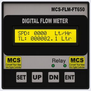
The meter uses a backlit 16×2 LCD for clear reading in normal industrial lighting. The top line shows the instant flow rate, while the bottom line shows the totalized volume in litres. In the source configuration, the flow rate is shown as SPD: xxxx Lt/Hr and the total volume as TL: xxxxxxx.x Ltr. This layout gives operators a quick view of the current flow condition and the accumulated quantity at the same time.

Operation begins by connecting the compatible pulse-output sensor, wiring the 220 VAC, 50 Hz supply and verifying the relay contacts according to the panel design. Once the sensor starts generating pulses, the meter calculates the live rate and increments the totalizer. The internal memory retains the total volume during power failure, so the stored quantity is not lost when supply is interrupted and restored later.

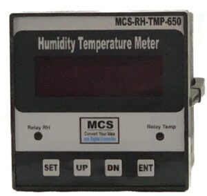
The front keys SET, UP, DN and ENT are used for field configuration. These keys make it possible to adjust the K-factor, review parameters and set the control logic from the front panel. Password protection is provided for important settings so that accidental changes are less likely after commissioning. That is especially useful on plant floors where several operators may have access to the same control cabinet.

For batch or fill applications, the relay outputs can be assigned to pump or valve control, batch cutoff or alarm functions. For utility monitoring, they can be used as high- or low-flow alerts. The exact relay use should be matched to the process requirement during setup so that the panel behaves as intended when the line is running.

Relay use in practical panels

In a simple tank-filling system, one relay may be used to stop the pump when the set quantity has been reached, while another relay may provide an alarm or interlock condition. In a process line, the relay may instead indicate a low-flow or abnormal-flow situation. Because the outputs are configurable as potential-free contacts, the instrument can be integrated into a wide variety of control circuits at the panel level.

For OEM builders, this can reduce the number of separate devices needed on the front of the machine. For maintenance teams, a single display plus relay combination is easier to inspect than multiple instruments spread across the cabinet. The important point is to confirm the intended logic before wiring is completed.

Calibration and factory-style verification

Liquid Flow Meters depend on correct pulse-per-litre calibration for accurate indication. During initial setup, the meter should be matched to the actual sensor output so that the displayed litres and flow rate reflect the real process volume. If the sensor type changes, the pipe size changes or the meter is moved to another line, the K-factor should be checked again.

A practical verification method is to compare the totalized reading against a measured reference volume or another trusted process benchmark. This is useful in RO and DM plants, water transfer lines, chemical dosing systems and batch applications where quantity control matters. The flow meter itself does not replace proper process checking; rather, it becomes reliable when the sensor signal and calibration are correct.

During commissioning, it is also sensible to confirm that the sensor orientation, cable routing and electrical connections are correct. If the display is not matching the expected flow, the first checks should usually be sensor wiring, pulse compatibility, K-factor entry and actual liquid movement through the line. This practical sequence often solves issues faster than changing the instrument.

For repeatable production work, a documented setup sheet is useful. Note the sensor model, the final K-factor, relay use and any zeroing or reset steps. That record makes future maintenance easier and helps when the same Liquid Flow Meters model is installed on multiple machines or on a line that may be serviced by a different technician later.

Maintenance and safety precautions

The electronic unit itself is low-maintenance, but the connected flow sensor requires periodic attention. Keep the sensing element free from debris or blockage, inspect cable connections, and confirm that the terminals remain tight. Because these meters are often installed in industrial panels, safe isolation during wiring, testing and replacement should always be followed.

If the meter is used near pumps, motors or other electrically noisy equipment, good cable routing and grounding practices are important. The installation should also stay within the normal environmental expectations of the panel, including temperature and humidity conditions suitable for the site. For critical process lines, periodic comparison of the totalizer with a measured reference volume is recommended.

When relay outputs are connected to a pump, valve or alarm circuit, test the output behavior in a controlled state before returning the system to service. This helps prevent unexpected start-up or shutdown events. The meter is intended for industrial use, but like any panel instrument it works best when the sensor, wiring and process line are all maintained properly.

Routine maintenance should therefore focus on the sensor and the surrounding electrical installation rather than the display module alone. In many cases, a brief inspection of the sensor body, connector, terminal tightness and totalizer consistency is enough to keep the system performing well.

Manufacturing origin, support and dispatch wording

Manufactured at UMA Industries’ unit in Village Sunped, Ballabgarh, Faridabad, Haryana, India, this product are positioned for buyers who prefer a direct manufacturer relationship. UMA Industries supplies and provides technical support to customers across India, which is useful for panel builders, OEM machine makers, maintenance teams and end users planning repeat orders or multi-site installation work.

Ready-stock compact products, controllers, spares and accessories may be dispatched by air courier within 3 working days, subject to availability, payment confirmation, destination serviceability and carrier schedules. Delivery timelines for complete salt spray chambers and other large equipment are confirmed separately according to model, capacity, packing and freight mode. For this product, the final dispatch method can be confirmed in the quotation or order discussion according to the requirement.

Related panel and instrumentation links

If your control panel also needs counting, timing or process-control functions, these related pages may be useful during planning:

These internal links can help buyers compare timing, counting and dosing functions when designing a broader control cabinet around this product.

Frequently asked questions

1. What are Liquid Flow Meters used for?

They are used to measure and display flow rate and total volume of water or other clean liquids when paired with a compatible pulse-output sensor. The meter shows the live rate and cumulative litres on the LCD.

2. Which sensors can be connected?

Pulse-output sensors such as turbine flow sensors, multi-jet water meters, reed-switch sensors and Hall-effect sensors can be used, provided the correct K-factor is entered during calibration.

3. Can the same meter be used for different pipe sizes?

Yes. The electronics are the same, while the pulses-per-litre setting is adjusted to match the sensor and pipe arrangement. That makes the meter flexible for several compatible sizes.

4. What does the LCD show?

The display shows instant flow rate on the top line and totalized volume on the bottom line. This makes the reading easy to understand during filling, pumping and transfer work.

5. Does the totalizer survive power failure?

Yes. The total volume is stored in internal memory, so the accumulated reading remains available after power returns.

6. What are the relay outputs for?

The two relay outputs can be used for batch control, pump or valve control, high or low flow alarm functions and similar panel logic, depending on the application.

Selection Guidance for Liquid Flow Meters

Use the front keys to enter the calibration menu and set the correct pulses-per-litre value for the connected sensor. After that, verify the reading against a known volume if the process is critical.

8. What maintenance is recommended?

Keep the sensor clean, check wiring tightness, verify grounding and periodically compare the totalized reading with a trusted reference volume or process benchmark.

9. Where is this product typically installed?

It is typically installed in RO, DM and softener plants, boiler and cooling water panels, chemical dosing skids, machine panels and other industrial control cabinets.

10. How can I prepare for a quotation?

Share the liquid type, sensor output, pipe size, panel space, required relay function and any preferred display or unit requirement. That helps UMA Industries confirm the appropriate configuration.

If you are specifying Liquid Flow Meters for a new panel or replacing an existing unit, UMA Industries can help align the sensor input, K-factor, relay use and mounting arrangement to the actual process requirement. The product is manufactured in Faridabad and supported across India for industrial water and clean-liquid applications.


Need help choosing? Call/WhatsApp us for industrial pH/ORP solutions.

Weight500 g
Dimensions12 × 11 × 11 cm

Reviews

There are no reviews yet.

Be the first to review “Liquid Flow Meters Manufacturer”
🟢 WhatsApp Price 📞 Call Now
Scroll to Top